MPLS L3VPN
ccnp-routing
Why MPLS L3VPN uses VRFs, route distinguishers, and route targets to keep customer routes separate, plus how packets flow across the provider core.
- L3VPN is an MPLS application that allows incredibly flexible and scalable customer VPNs to be built over a common MPLS infrastructure.
- L3VPN uses a peer to peer VPN model as opposed to legacy overlay models.
- L3VPN is extremely flexible to many different customer needs.
Big Picture
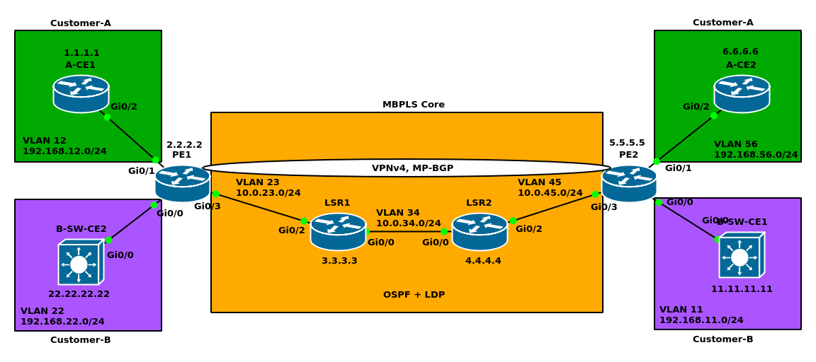
- We have Customer-A and Customer-B each having 2 sites. We want to make Customer-A sites reachable to each other, and likewise for Customer-B. But we do not want them to see each other’s site.
- MPLS L3VPN is configured on PEs.
- Customer can choose whatever subnets they want.
- Problem #1: What if customers choose the exact same subnets?
- Solution #1: Make VRFs on each PE, one per customer. In this case we need 2 VRFs on each PE.
- Problem #2: How should the PE distinguish between same subnets it receives from customers?
- Solution #2: Route distinguisher. Assign a unique RD for each VRF.
- Problem #3: We configure a VRF per customer on each PE. How about other LSRs in the LSP?
- Idiotic Solution: Configure VRFs on all routers in our LSP
- Solution #3: using a routing protocol which does not need direct connectivity to make a neighborship (iBGP). BGP is designed for advertising 32-bit IPv4 not for VPNv4 which is 96 bits. With MP-iBGP VPNv4 prefixes are sent to other PEs.
- Problem 4: We have MP-iBGP in the SP, remember that when we configured BGP neighborship we had to inject routes into the BGP either using network command or redistribution.
- Solution 4-1: Use VRF eBGP between CE and PE to insert the customer prefixes.
- Solution 4-2: Static route between CE and PE then redistribute it into our MP-BGP.
- Here is what happens in the data plane:
- Customer-A sends a regular IPv4 packet destined for a CE2 network to PE1
- PE1 looks up the route in the customer specific VRF routing table
- PE1 pushes MPLS label on the stack and sends to the MPLS network
- Packet is label switched through the MPLS network and reaches PE2
- PE2 places packet into the correct VRF
- PE2 looks up route in the customer specific VRF routing table
- PE2 sends a regular IPv4 packet to Customer-A toward the final destination network
Virtual Routing and Forwarding (VRF)
- VRFs are effectively splitting a single physical router into many virtual routers, with each VRF having its own dedicated interfaces, RIB, FIB, and CEF table.
- VRFs separate customer routing information.
- Each customer is assigned a VRF.
- eBGP, IGP, or static routing is configured per VRF on the PE.
- The customer CE device has no idea it is part of a VRF, and operates just like any other normal router.
- A VRF is defined on a PE router by four different things.
- VRF name
- Route Distinguisher (RD): used to uniquely identify a customer prefix
64-bit number in the format ASN:nn or IP:nn
VPNv4 = RD (64 bits) + IPv4 32 (bits)
For example:
PE1 VRF PE1 VPNv4 VRF A Site 1 64500:100:192.168.1.0/24 VRF B Site 5 64500:200:192.168.1.0/24
- What interfaces are assigned to the VRF
- Route Target (RT): an extended BGP community attached to each VPNv4 route.
- If used, RD is not considered by router
- Imported RT: determines which VPNv4 routes are imported to the VRF
- Exported RT: determines what RT will be attached to route redistributed into MP-BGP
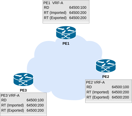
- In full mesh scenarios RD, Imported RT, and Exported RT have the same value.
- We can design different topology playing with RT values
- Full Mesh
full mesh mpls - Hub and Spoke
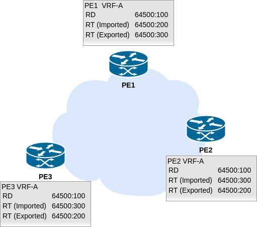
hubandspoke - Exercise: Design a hybrid topology wherein we have 2 customers and headquarters can see each other. Branches can see their headquarters.
PE-CE routing
- Customer CE devices will directly connect to PE device using an L3 link.
- Customer and SP will run static routing, an IGP, or eBGP on the PE-CE link.
- CE device is generally not VRF aware, but could be in advanced cases VRF lite!
- PE routers partition each customer into their own VRF to keep routing private.