Private VLAN
It is like the nesting concept of creating VLANs inside a VLAN. As we know, Ethernet VLANs are not allowed to communicate directly with each other; they need some Layer three (L3) devices (like a router, a multilayer switch, etc.) to forward packets between the broadcast domains.
The same concept is applicable to the PVLANs. Since the sub-domains are segregated at level 2, they need to communicate using an upper level (L3 and packet forwarding) entity, such as a router. Regular VLANs usually correspond to different IP subnets. But when we split a VLAN using PVLANs, hosts in different PVLANs still belong to the same IP subnet, but they need to use a router (another L3 device) to talk to each other.
How PVLAN helps us
We want to put multiple servers into the same IP subnet and provide a good level of isolation between them. Besides this it is also helpful to provide isolation at Layer 2 as a security measure.
- We want all servers to communicate with Directory Service on VLAN200 (Primary VLAN)
- We want servers in VLAN 20 to communicate with each other (Community VLAN)
- We do NOT want servers in VLAN 30 to communicate with each other (Isolated VLAN)
PVLAN Port Types
There are three types of PVLAN ports:
- Promiscuous (P): Usually connects to a router or, in our example, a directory server. It is a type of port which is allowed to send and receive frames from any other port on the VLAN.
- Isolated (I): This type of port is only allowed to communicate with P ports; they are “stub” ports. This type of port usually connects to hosts or, in our example, to two servers which we do not want to have communication in between. There can be only 1 isolated VLAN per PVLAN.
- Community (C): Community ports are allowed to talk to their buddies, i.e. Community ports.
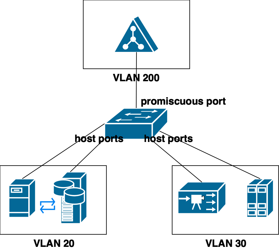
- Primary VLAN (VLAN 200 in our example): Simply the original VLAN (VLAN 200 in our example). This type of VLAN is used to forward frames downstream from P ports to all other port types (I and C ports). Primary VLAN entails all ports in the domain, but is only used to transport frames from router to hosts (P to I and C).
Configuration
- Step 1: issue
vtp mode transparentas the PVLANs do not work with VTP. - Step 2: Create secondary VLANS
SW1(config)#vlan 20
SW1(config-vlan)#name Community_VLAN
SW1(config-vlan)#private-vlan community
SW1(config-vlan)#exit
SW1(config)#vlan 30
SW1(config-vlan)#name Isolated_VLAN
SW1(config-vlan)#private-vlan isolated
SW1(config-vlan)#exit- Step 3: Create primary VLAN and associate VLANs 20 and 30 to it
SW1(config)#vlan 200
SW1(config-vlan)#name Primary_VLAN
SW1(config-vlan)#private-vlan primary
SW1(config-vlan)#private-vlan association 20,30
SW1(config-vlan)#exit- Step 4: Determine interface types (promiscuous or host) on the interfaces’ level:
SW1(config)#interface fa 1/0/1
SW1(config-if)#switchport mode private-vlan promiscuous
SW1(config-if)#switchport private-vlan mapping 200 20,30
SW1(config-if)#exit
SW1(config)#int range fa 1/0/2 - 3
SW1(config-if-range)#switchport mode private-vlan host
SW1(config-if-range)#switchport private-vlan host-association 200 20
SW1(config-if-range)#exit
SW1(config)#interface range fa 1/0/4 - 5
SW1(config-if-range)#switchport mode private-vlan host
SW1(config-if-range)#switchport private-vlan host-association 200 30
SW1(config-if-range)#exit
Verification
SW1#show vlan private-vlan

Primary Secondary Type              Ports
------- --------- ----------------- ------------------------------------------
200     20        community         Fa1/0/1, Fa1/0/2, Fa1/0/3
200     30        isolated          Fa1/0/1, Fa1/0/4, Fa1/0/5
SW1#show vlan brief
VLAN Name Status Ports
---- -------------------------------- --------- -------------------------------
1 default active Fa1/0/6, Fa1/0/7, Fa1/0/8
Fa1/0/9, Fa1/0/10, Fa1/0/11
Fa1/0/12
20 Community_VLAN active
30 Isolated_VLAN active
200 Primary_VLAN active
1002 fddi-default act/unsup
1003 trcrf-default act/unsup
1004 fddinet-default act/unsup
1005 trbrf-default act/unsup
SW1#show interfaces status

Port      Name               Status       Vlan       Duplex  Speed Type
Fa1/0/1                      connected    200        a-full  a-100 10/100BaseTX
Fa1/0/2                      connected    200,20     a-full  a-100 10/100BaseTX
Fa1/0/3                      connected    200,20     a-full  a-100 10/100BaseTX
Fa1/0/4                      connected    200,30     a-full  a-100 10/100BaseTX
Fa1/0/5                      connected    200,30     a-full  a-100 10/100BaseTX
PVLAN Edge (Protected Port)
The PVLAN edge (protected port) is a feature that has only local significance to the switch (unlike Private VLANs), and there is no isolation provided between two protected ports located on different switches. A protected port does not forward any traffic (unicast, multicast, or broadcast) to any other port that is also a protected port in the same switch. Traffic cannot be forwarded between protected ports at L2, all traffic passing between protected ports must be forwarded through a Layer 3 (L3) device.
Switch(config)#interface range fastEthernet 3/0/1 - 12
Switch(config-if-range)#switchport protected
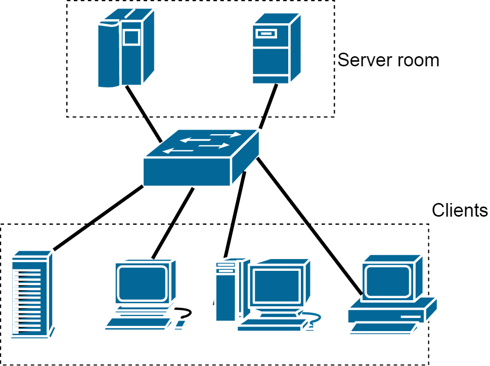
Protected ports cannot see each other, but they can see the unprotected ports. Scenario (Server Room): We do not want clients to see each other but the server.
Switch#show interfaces status err-disabled